


Article / Case Studies
1University of Applied Sciences of Southern Switzerland, DACD, SUPSI, via F. Ruchat-Roncati 15, 6850 Mendrisio, Switzerland.
C. Paglia
University of Applied Sciences of Southern Switzerland,
DACD, SUPSI,
via F. Ruchat-Roncati 15,
6850 Mendrisio,
Switzerland.
9 February 2023 ; 27 February 2023
Asphalt rutting is a major permanent degradation issue caused by the high temperature and the cyclic load of vehicles along roadways. In this work, a highway slow lane within a tunnel was affected by a relevant deformation in a relatively short time. The investigation focused on a 200 m road distance. Benkelman deflection tests on the road surface, measurements of the depth of the road deformation, particle-size distribution of the road base, Proctor and CBR tests were performed. The unbinded underground material matched the required limits. Moreover, a concrete basement with a thickness up to 60 cm was present between the upper bituminous layers and the unbinded sub-base. The concrete increased the stiffness of the whole pavement system. The road base exhibited a good bearing capacity, while the reason for the rutting needed to be found in the middle and lower bituminous layers, in spite of the wide curvature of the permanent deformation.
Keywords : asphalt, rutting, highway tunnel, pavement.
Asphalt pavements exhibit permanent deformation during high temperature exposition and traffic load. Rutting is caused by a material consolidation and a lateral movement promoted by the repeated heavy wheel loadings. The distress exhibits depressed ruts along the wheel paths on the pavement surface. This type of distress is not directly related to a structural failure but can be considered as a serious safety hazard to vehicles. During rainfall, water can accumulate along the rut depressions and cause hydroplaning. Moreover, the vehicles tend to be pushed towards the rut path, making the driving a difficult issue (Thom, 2014). The rutting causes longitudinal surface depressions within the wheel path and may cause transverse displacement, thereby reducing the serviceability and safety of a flexible pavements. It can be the result of a permanent reduction in the material volume due to the mechanical traffic consolidation and densification, a permanent movement of the material at constant volume caused by the plastic shear, or a combination of both actions. These distresses are correlated with the time, temperature, and stress dependent behaviour of bituminous materials. In fact, when asphalt concrete is subjected to repeated loading, it exhibits elastic / visco-elastic / plastic responses. The elastic properties are related to the modulus of elasticity and Poisson’s ratio, and they do not contribute to permanent deformation. The plastic properties contribute to the irreversible deformation, which is cumulative under repeated loading (Thom, 2014; Rashad& Tarefder, 2020).
Major rutting is attributed to the decrease in thickness of middle and lower layers. Vehicle speed, time and tyres-road contact pressure may also be accounted for it. Inadequate material compaction, wrong aggregate gradation or aggregates with low strength and hardness, bituminous migration and excessive content, high quantities of fine-grained aggregate components as well as high percentages of natural rounded aggregate particles are the major distress causes (Xu & Huang, 2012; Button et al., 1990). Shear resistance properties of the bituminous materials need to be properly addressed for limiting the rutting, while pavement structural design practices mainly focused on protecting the subgrade by excessive vertical strain, the shear resistance of the bituminous layers was left to mixture designers.
A highway tunnel approximately 2 km long exhibited rutting along the slow lane in a relatively short time. The rutting was concentrated along the surface within a 200 m long distance and was particularly intense in a 10 m road section close to the tunnel entrance. The distress was restored, but after 8 months rutting formed again. The reason was supposed to be in the undelaying pavement layers. Therefore, the aim of this work was to analyze the extent of the rutting and to clarify the road base material properties.
A visual ad optical inspection was done on site. Furthermore, 20 Benkelman deflection tests were done every 10 m on the 200 m road section along the slow lane left tyre area at temperatures ranging from 18.4 and 20.3 C (Swiss organization of road and traffic construction, 2019). Along the 200 m section, 2 samples of the road base were taken and the particle-size distribution (Norm SN 670 340-4 Geotechnical investigations – Laboratory tests on ground samples – Part 4: Granulometric distribution, 2018; Norm SN 670 816 Sedimentary test with areometry (mineral granulates) – repealed normative), the Proctor test (Norm SN 670 330-2a Unbinded and hydraulic binded mixtures – Part 2: tests for laboratory reference density and water content – Proctor compaction, 2015; Norm 670 119-NA Unbinded mixtures. Technical requirements, 2021), the California bearing ratio test CBR1 and the CBR2 tests were done to evaluate the strength of the soil subgrades and the base course materials (Norm EN 13286-47 Unbinded and hydraulic binded mixtures, part 47: (CBR) California bearing ratio, direct bearing index (IBI) and linear theshold values, 2022).
The stratigraphy of the pavement consisted of an asphalt concrete AC 16 H PmB modified with polymers that restored an existing stone matrix asphalt SMA 11 with rutting. The SMA 11 surface course exhibited a compaction degree, macropores content and granulometric curves that respected the required limits. The binder as well as the base layer types were unknown. The bituminous top layer exhibited a thickness of 45-55 mm, the middle layer 40-45 mm and the base layer 40-45 mm. The layers can be partially identified with the color difference, with some partial detachments at the interfaces. Underneath the bituminous layers, an unreinforced concrete basement was present (Fig. 1 left). Below the cement-based material an unbinded granulate layer was used to level the rock basement. In fact, rock were partially present along the high-low speed lanes. The changes in the underground characteristics may emphasize the damage and lead to fracture along the depression. Unbinded granulates were partially observed underneath the rutting.
A visual inspection of the pavements indicated a clear rutting of the surface (Fig. 1 right).
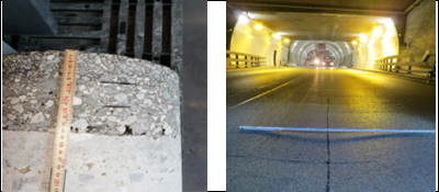
Figure 1: (Left) Pavement stratigraphy. (Right) Rutting along the highway lane.
The rutting indicated a maximum depth variation between 18-21 mm with a middle degradation degree (Tab. 1-2).
| Distance from the middle lane [cm] | Rutting depth [mm] |
|---|---|
| 10 | 0 |
| 20 | 6 |
| 40 | 16 |
| 50 | 18 |
| 80 | 10 |
| 100 | 0 |
| 140 | 0 |
| 170 | 7 |
| 210 | 6 |
| 230 | 7 |
| 250 | 8 |
| 270 | 6 |
| 290 | 0 |
| Distance from the middle lane[cm] | Ruttig depth [mm] |
|---|---|
| 20 | 0 |
| 40 | 13 |
| 60 | 21 |
| 70 | 21 |
| 90 | 12 |
| 120 | 0 |
| 140 | 0 |
| 170 | 8 |
| 210 | 6 |
| 230 | 7 |
| 250 | 9 |
| 260 | 10 |
| 280 | 7 |
| 300 | 0 |
Table 1: (top) and 2 (bottom). Measurements of the rutting depth at several distances from the middle lane in two zones.
The deflection measurements exhibited a mean value of 53.5 (d) [1/100 mm] with a standard deviation of 17.1 (σ) [1/100 mm] and a variation coefficient of 32.1 [%]. The resulting deformation determined for the traffic load T5 (Norm VSS 40 733 b, Road maintenance, reinforcement of the bituminous structure based on deflection measurements, 2019) and for T6 traffic load (Norm VSS 40 324 Road design, sub-base, base and surface course, 2019) could be calculated according to the table 3. The restoration thickness to be applied ranged between 12-14 cm (Norm VSS 40 733 b, Road maintenance, reinforcement of the bituminous structure based on deflection measurements, 2019).
| Section | 10 < H asf < 15 CM | H asf > 15 CM |
|---|---|---|
| Deflection | 99.1 | 90.3 |
| Parameter C | 1.13 | 1.03 |
Table 3: Requirements and parameters according to normative (Norm VSS 40 733 b, Road maintenance, reinforcement of the bituminous structure based on deflection measurements, 2019).
The particle size distribution analysis of the unbinded layer underneath the concrete taken at a depth of 80 cm (Fig. 2 left) exhibited a slight lack of coarse grains (Fig. 2 right). This fact may be due to the rolling breaking of the aggregate components during the service life. The fine components fitted a little better the required limits. The fraction (0.063 mm) exhibited 4.8 %, while the limit was set at 12%.
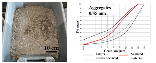 Figure 2: Analyzed unbound material (left) and particle size distribution (right).
Additional analysis fitted a little better the required limits. In this case, the fine component (0.063 mm) indicated 3.4 % and the required limit remained 12% (Fig. 3).
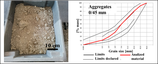 Figure 3: Analyzed unbound material (left) and particle size distribution (right).
The CBR1 and CBR2 requirements showed a value ≥ 40% and the water resistance must satisfy the relation CBR2/CBR1 ≥ 0.5 (Norm VSS 70 119 Unbinded mixtures. Technical requirements, 2021). An additional normative (Norm VSS 40 324 Road design, sub-base, base and surface course, 2019) indicates a CBR > 25% for a load bearing capacity S4 (high level). The measurements of one sample indicated a maximum density of 2.195 t/m3 with an optimal water content of 7.8% (Proctor). Afterwards the CBR was performed to evaluate the load bearing capacity. The CBR1 (sinking 5.0 mm) of 40.4% was superior to the norm requirement. The measured CBR2 of 31.2% was lower than the norm requirement. The water resistance CBR2/CBR1 was equal to 0.77 and complied with the minimum required for a high load bearing capacity class S4. The other specimen reached the maximum density of 2.146 t/m3 with an optimal water content of 8.3% (Proctor). The CBR1 (sinking 5.0 mm) was equal to 29.9% and was lower than the value required from the norm. The CBR2 was 26.5% and was lower than required from the norm.
The water resistance CBR2/CBR1 exhibited a value of 0.89 and complied the minimum required. The CBR values were both higher than the minimum required for the load bearing class S4 with 25%.
The measured values of the unbounded road base showed a high load bearing capacity. Wide rutting depression marks are usually considered for an insufficient load bearing capacity of the road base, while narrow depressions and transversal material transport for soft and low load bearing capacity of the bituminous surface courses (Washington asphalt paving association (WAPA), 2023). Nevertheless, the relative wide curvature and depression seen of the pavement surface, was not caused by an insufficient load bearing capacity of the base, but rather from the upper bituminous layers.
The restoration of the situation was done by milling the bituminous layer down to 130 mm and by placing an asphalt concrete with a macro roughness AC MR 11 (40 mm) with a polymer modified bitumen PmB 45/80-65 E fibre reinforced (Aramid monofilament dosage 500 g/t asphalt by mass). A stress absorption membrane interlayer SAMI with water sealant purpose with a thickness of 10 mm and a high modulus of elasticity asphalt concrete AC 22 EME C1 (80 mm) with a bitumen B 15 / 25 fibre reinforced, that means a more rigid asphalt concrete layers was also placed.
The rutting was seen along a road interval with a total thickness of the pavement stratigraphy of almost 30 cm that was widely superior compared to other road sections, where no rutting was observed. That means the rutting was not systematically related to the pavement stratigraphy thickness. Within 200 meters, the stratigraphy varied significantly. Bituminous layers as well as underlying concrete and the concrete / rock basement varied a lot. The granulometric curves of the unbinded underground material respected the limits, although they exhibited a slight lack of coarse component. This may be due to the crushing of the coarse aggregate during the rolling and compacting of the material during the placing works. Nevertheless, the material exhibited high load bearing capacity. The reason of rutting for the traffic class T 6 needed to be find in the bituminous layers, in particular the middle and lower layer, since the load bearing capacity of the unbinded material was high. In addition, a concrete basement with a significant thickness was present between the upper bituminous layers and the unbinded sub-base layers. The concrete increased the stiffness of the whole pavement system.
The authors would like to thank the technicians of the Institute of materials and construction Supsi and the Institute of materials mechanics for the sampling and the measurements.
-
- Thom, N. (2014). Principles of pavement engineering (2nd edi). ICE Publishing. Retrieved from https://store.saice.org.za/book-store/principles-of-pavement-engineering-second-edition
- Rashad, M. I. & Tarefder, R. A. (2020). Pavement design, Materials analysis and highways (1st edition). Mc Graw Hill. Retrieved from https://www.accessengineeringlibrary.com/content/book/9781260458916
- Xu, T. & Huang, X. (2012). Investigation into causes of in-place rutting in asphalt pavement. Construction and Building Materials, 28(1), 525-530. DOI: https://doi.org/10.1016/j.conbuildmat.2011.09.007
- Button, J. W., Perdomo, D. & Lytton, R. L. (1990). Influence of Aggregate on Rutting in Asphalt Concrete Pavements. Transportation research record, 1259, 141-152. Retrieved from https://onlinepubs.trb.org/Onlinepubs/trr/1990/1259/1259-013.pdf
- Swiss organization of road and traffic construction, VSS 70 362 Upper courses reinforcements, Deflection measurements, 2019.
- Norm SN 670 340-4 Geotechnical investigations – Laboratory tests on ground samples – Part 4: Granulometric distribution, 2018.
- Norm SN 670 816 Sedimentary test with areometry (mineral granulates) – repealed normative.
- Norm SN 670 330-2a Unbinded and hydraulic binded mixtures – Part 2: tests for laboratory reference density and water content – Proctor compaction, 2015.
- Norm 670 119-NA Unbinded mixtures. Technical requirements, 2021.
- Norm EN 13286-47 Unbinded and hydraulic binded mixtures, part 47: (CBR) California bearing ratio, direct bearing index (IBI) and linear theshold values, 2022.
- Norm VSS 40 733 b, Road maintenance, reinforcement of the bituminous structure based on deflection measurements, 2019.
- Norm VSS 40 324 Road design, sub-base, base and surface course, 2019.
- Norm VSS 70 119 Unbinded mixtures. Technical requirements, 2021.
- Washington asphalt paving association (WAPA). (2023). WAPA & Industry Events Dates. Retrieved from https://www.asphaltwa.com/2021-wapa-industry-events/